Insertion Loss You Can Trust: Reading a Splitter Datasheet
- Share
- publisher
- SOMI Engineering
- Issue Time
- Nov 5,2026
Summary
A splitter datasheet that says 5-2500MHz tells you almost nothing. What matters is insertion loss band by band, isolation between ports and return loss at the edges. This guide reads a real 2.6GHz splitter specification, explains where the 4.2 to 7.8 dB range comes from, and lists what to request before you approve a batch.
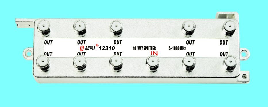
For a two-way passive splitter, 3.5 to 4.5 dB insertion loss at the low band is normal, rising to roughly 7 to 8 dB at 2.4 GHz. A four-way splitter adds about 3.5 dB on top of that. Anything advertised as 5-2500 MHz without band-by-band figures is a marketing range, not a specification: the loss at 2.4 GHz can be double the loss at 50 MHz, and that difference decides whether the last outlet in a long run still works. Ask for the loss table per band, the isolation figure and the return loss, then test one sample against it.
A frequency range is not a specification
Almost every splitter listing carries a phrase like 5-2500 MHz. It states where the device is claimed to function, not how well it behaves anywhere inside that window. Passive splitters are built from ferrite transformers and compensation networks, and their performance is never flat: loss climbs with frequency, isolation falls, and return loss degrades at the band edges where the transformer runs out of coupling.
Reviewers who measure splitters rather than read labels keep making the same point: a printed range with no per-band numbers cannot be used to design a distribution. If the datasheet does not tell you the loss at 2.4 GHz, assume it is the worst number in the table, because that is what the installer will experience on a satellite IF run.
Where 4.2 to 7.8 dB comes from
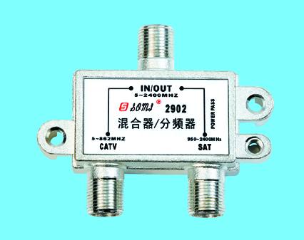
A 2-way splitter divides power into two paths, so the theoretical minimum loss is 3.0 dB per port plus a small insertion loss. Real devices add transformer loss, and the addition is frequency dependent. On the SOMI 2202 2.6 GHz splitter the published insertion loss is 4.2 dB at the bottom of the band and 7.8 dB at 2400-2600 MHz, which is a 2.6 GHz part behaving like a 2.6 GHz part rather than a 1 GHz part with optimistic print.
That 3.6 dB spread is not a defect. It is the honest shape of a passive network, and it matters twice: once when you calculate whether the last outlet still has enough level, and once when you compare two suppliers who both claim 'low loss'. A supplier who quotes a single figure is quoting the best band and hiding the worst.
| Band | Insertion loss (2202) | Isolation | What it means on site |
|---|---|---|---|
| 5-40 MHz | 4.2 dB | 18 dB min | Return path and band 0 legacy services pass with least loss |
| 40-1000 MHz | 4.4-5.6 dB | 20 dB min | Terrestrial TV band; the working range for most installations |
| 1000-1750 MHz | 5.8-6.8 dB | 20 dB min | Satellite IF low band |
| 1750-2400 MHz | 6.8-7.4 dB | 19 dB min | Satellite IF high band |
| 2400-2600 MHz | 7.8 dB max | 18 dB min | Top of band; plan the level budget with this number |
Isolation and return loss decide whether the picture is clean
Insertion loss is only the first column. Isolation between output ports keeps one receiver's local oscillator and reflected energy out of its neighbour, which is what prevents a satellite receiver from disturbing the terrestrial feed on the same splitter. Return loss describes how well each port is matched: a poor match reflects signal back up the cable, producing standing waves and visible ghosting on analogue channels, and raising the error rate on digital multiplexes.
A practical acceptance threshold is 18 dB or better for isolation and 10 dB or better for return loss across the working band. Below that, installers start seeing symptoms they attribute to the cable, the aerial or the receiver, when the splitter is the common factor.
There is a second-order effect that rarely appears on a datasheet: what happens when one port is left open. An unused output that is not terminated reflects the full signal back into the network, which degrades isolation for every other port. Splitters used in cabinets where outlets are added later should be specified with the expectation that some ports stay unterminated for months, and the isolation figure should be read as the worst case rather than the typical one.
How to specify a splitter you can defend
The point of a specification is to give you something to reject a delivery against. That requires numbers per band, a stated test method and a sample you have measured yourself. When those three exist, a price difference between two suppliers becomes a decision about construction rather than a guess about quality.
- Request insertion loss per band, not a single typical value.
- Request isolation minimum, not typical.
- Request return loss at the band edges, where it is worst.
- Ask for the housing material and the shielding figure in dB.
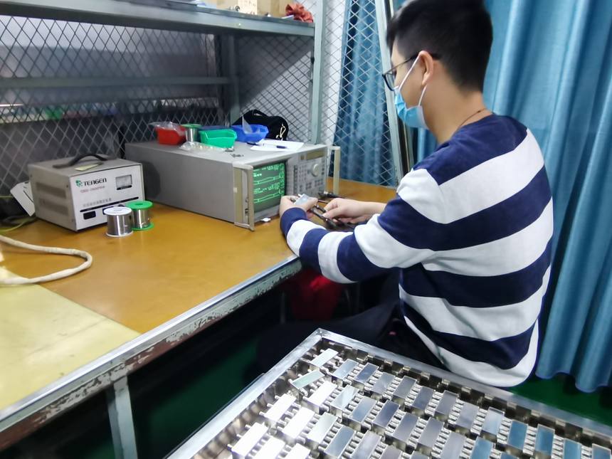
- Measure one sample from the first delivery against the table before releasing the batch.
- For satellite IF distribution, confirm the part is specified to 2400 MHz rather than 2150 MHz.
The cost of a missing number
A splitter that loses 7.8 dB where the design assumed 5 dB shows up as one weak outlet at the end of a chain, and the installer compensates by raising amplifier gain. That raises the noise floor for every other outlet. The 3 dB that was not in the datasheet becomes a service call, and the service call costs more than the price difference between a specified splitter and an unspecified one. Detailed loss tables for the full range sit on our TV signal splitter pages, including the satellite IF versions that run to 2.6 GHz.
Need this checked against your own signal chain?
If you are comparing splitter quotations, send us the band plan and the number of outlets and we will return a loss budget with the model numbers that meet it. Send the details through our inquiry form or reach the team on the contact page.
Request a quotation