Amplify Near the Aerial, Split Passively Near the TVs
- Share
- publisher
- SOMI Engineering
- Issue Time
- Nov 9,2026
Summary
Most weak-signal complaints are wiring problems, not signal problems. The working rule is simple: apply gain as early as possible, then distribute passively as close to the receivers as possible. This article explains why over-amplification lowers the signal-to-noise ratio, walks through three typical topologies and lists the installation errors that produce callbacks.
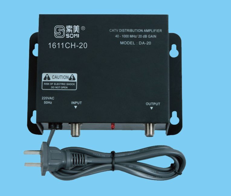
Put the amplifier as close to the aerial as the installation allows, and put the splitters as close to the televisions as the cable run allows. Gain applied at the aerial lifts the signal while the noise contribution of the downlead is still small; gain applied at the far end lifts the noise the cable has already added. Passive splitting near the receivers keeps the amplified signal at full strength for as long as possible, so each outlet receives the highest level the system can deliver.
Signal-to-noise ratio is set at the first stage
Every device in a chain adds noise, but the first device dominates. If a masthead amplifier with a 2 dB noise figure is installed at the aerial, the noise contribution of the following 20 metres of coax is divided by the gain of that amplifier and becomes almost irrelevant. If the gain is applied at the far end of the same cable, the cable's loss is added to the signal before any amplification, and the noise figure of the whole system rises by the loss of the cable.
This is why a 20 dB amplifier at the aerial can outperform a 30 dB amplifier in the lounge. The second one has more gain, but it is amplifying a signal that has already lost 10 dB in the downlead, together with whatever interference the cable picked up on the way.
There is a second reason to amplify early: digital reception has a cliff rather than a slope. Above the threshold, a multiplex is perfect; below it, the picture disappears entirely. An installation with 3 dB of margin looks flawless until a wet leaf or a new wall attenuates the path, and then it fails without warning. Amplifying at the aerial buys margin where margin is cheapest, because the gain is applied before the loss rather than after it.
Why over-amplification makes the picture worse
Gain does not improve the ratio between signal and noise; it multiplies both. What it can do is push the output stage into compression, at which point intermodulation products appear inside the band and the effective noise floor rises. The symptom is a picture that is strong on the meter and poor on the screen, which sends installers looking for a better aerial when the amplifier is the cause.
- Output level above the rated figure: the first sign of compression, often reached only in the evening.
- Gain set to maximum for convenience: every amplifier should be set to the level the outlets need, not to its limit.
- Cascading two amplifiers in series: the second one amplifies the noise of the first and adds its own.
- Unterminated splitter ports: reflections that degrade isolation and raise the noise floor on every outlet.
Topology one: single dwelling, long downlead
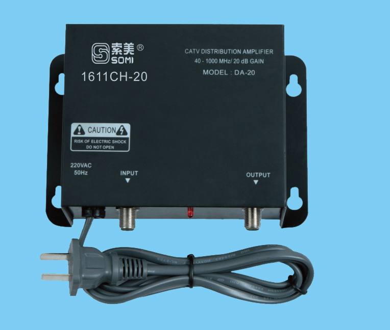
A detached house with the aerial on a gable and a 25 metre run to a central cabinet needs the gain at the aerial end. A masthead amplifier with a 20 dB gain and a noise figure below 3 dB feeds the downlead, and a passive splitter in the cabinet distributes to four outlets. With 6 dB of cable loss and a 7 dB split, each outlet still receives a level well above the digital threshold, and the system has margin for a fifth outlet.
| Stage | Device | Level change | Running level |
|---|---|---|---|
| Aerial output | Wideband aerial | reference | 62 dBuV |
| Masthead | 20 dB amplifier, NF 2.5 dB | +20 dB | 82 dBuV |
| Downlead | 25 m RG6 | -6 dB | 76 dBuV |
| Distribution | 4-way passive splitter | -7.5 dB | 68.5 dBuV |
| Outlet | Wall plate + fly lead | -1.5 dB | 67 dBuV |
Topology two: multiple dwellings, shared riser
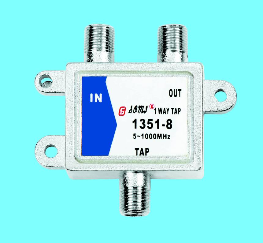
A building with a riser serving eight apartments cannot be fed from a single splitter without loss. The usual arrangement is a trunk amplifier at the head end, taps along the riser and a small splitter at each floor. Amplification happens once, at the head end, and every tap drops a fixed amount from a trunk that stays at a constant level. This is the topology that CATV taps are designed for, and the reason taps are specified with a through-loss and a tap-loss rather than a single insertion figure.
Topology three: satellite IF and terrestrial on one cable
When satellite intermediate frequency and terrestrial TV share a single cable, the splitter must be specified to 2400 MHz and the amplifier must pass both bands. A 1 GHz splitter used on an IF run loses more at the top of the band than the datasheet suggests, and the receiver loses the high-band transponders first. The satellite IF splitters and the 2601 satellite line amplifier cover 900 to 2200 MHz for this reason.
The installation errors that produce callbacks
Most return visits are caused by five recurring mistakes. None of them is exotic, and all of them are visible in a commissioning record if one is kept.
- Amplifier installed in the loft rather than at the aerial, adding the loft-to-aerial loss before any gain.
- Gain set by ear rather than by meter, leaving the output 10 dB above what the outlets need.
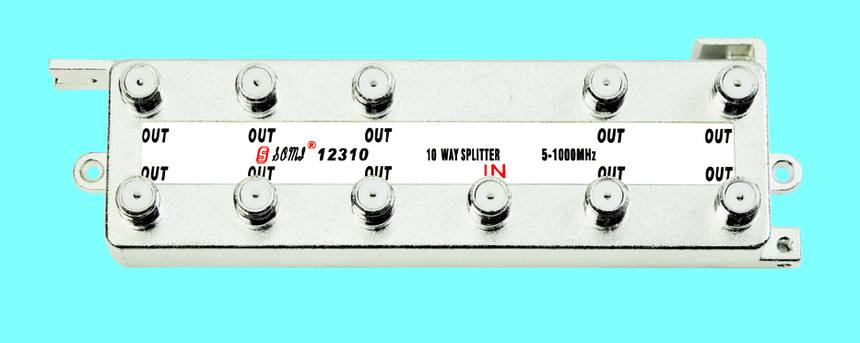
- Splitter installed at the head end and long cable runs to each outlet, wasting the amplified level in the cable.
- Fly leads with moulded plugs and no screening, coupling interference at the last metre.
- No commissioning record, so the next visit starts from zero.
Commissioning in five measurements
A commissioning record turns an installation into a documented system. The level at the aerial, the level after the amplifier, the level at the furthest outlet, the noise margin on the weakest multiplex and the amplifier model with its gain setting are enough to diagnose any future complaint without returning to first principles.
Need this checked against your own signal chain?
Give us the cable lengths and the number of outlets and we will return a level budget with the amplifier and splitter models that satisfy it. Send the details through our inquiry form or reach the team on the contact page.
Request a quotation