2.6GHz Splitters: Distributing Satellite IF Together with Terrestrial TV
- Share
- publisher
- SOMI Engineering
- Issue Time
- Nov 12,2026
Summary
A splitter rated to 1 GHz will pass satellite intermediate frequency and lose more at the top of the band than its datasheet admits. This article explains the 950-2400 MHz IF window, why a 2.6 GHz part behaves differently, how to read the loss at 2400 MHz, and how to combine satellite and terrestrial feeds without degrading either.
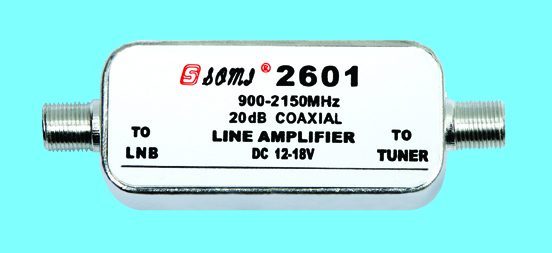
Satellite intermediate frequency occupies roughly 950 to 2150 MHz, and modern LNBs and multiswitches extend usable operation towards 2400 MHz. A splitter specified only to 1000 MHz will pass a satellite signal, but its loss and isolation at 2000 MHz are outside any guaranteed value, so the highest transponders fail first. Specify a splitter rated to 2400 or 2600 MHz with published loss at the top of the band, and keep terrestrial and satellite combining ahead of the split, not after it.
Two bands, one cable, different rules
Terrestrial television lives between 470 and 790 MHz. Satellite intermediate frequency starts around 950 MHz and runs to 2150 MHz for a universal LNB, with wideband and multiswitch systems pushing higher. A splitter sees both, and its behaviour is not uniform across that span: loss rises with frequency, isolation falls, and the port match degrades as the ferrite transformer approaches its limit.
The practical consequence is that the outlet which works perfectly on terrestrial channels can lose the high-band transponders while the low band survives. Installers read that as a dish alignment problem, replace the LNB, and find the fault was in a splitter that was never specified above 1 GHz.
Why a 1 GHz splitter is not a satellite splitter
A splitter designed for terrestrial distribution is optimised around 500 to 800 MHz. Its transformer and compensation network are chosen for that window. Push it to 2150 MHz and two things happen: the insertion loss climbs beyond the published figure, and the isolation between ports drops, so one receiver's LNB supply and local oscillator leakage reach its neighbour.
None of this appears as a hard failure. It appears as a receiver that takes longer to lock, a transponder that drops out in rain, or a multiswitch that resets when a second receiver powers up. The device is working; it is simply being used outside the range it was designed for.
Reading the loss at 2400 MHz
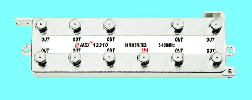
The SOMI 2202 2.6 GHz splitter publishes insertion loss band by band: 4.2 dB at the bottom of the band, 5.8 to 6.8 dB through the low IF range, 6.8 to 7.4 dB in the 1750-2400 MHz window and 7.8 dB maximum at 2400-2600 MHz, with isolation of 18 to 23 dB across the range. Those numbers let an installer build a level budget that includes the worst case rather than the brochure case.
| Service | Frequency | Typical level at splitter input | Loss to plan with |
|---|---|---|---|
| Terrestrial multiplexes | 470-790 MHz | 60-75 dBuV | 4.4-5.6 dB |
| Satellite low band | 950-1950 MHz | 50-60 dBuV | 5.8-7.0 dB |
| Satellite high band | 1950-2150 MHz | 50-60 dBuV | 7.0-7.4 dB |
| Wideband LNB output | up to 2400 MHz | 45-55 dBuV | 7.4-7.8 dB |
Combining satellite and terrestrial without degrading either
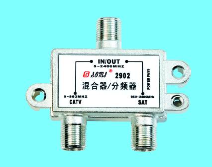
When one cable carries both services, the combining point matters as much as the splitter. Combining at the head end, before the split, means every outlet receives the same mixed signal and every splitter in the chain must be rated to the highest frequency present. Combining at the outlet, with a diplexed wall plate, keeps the satellite run separate but requires a wall plate that passes DC and does not attenuate the IF band.
Wideband LNBs make the rating question sharper. A wideband output covers the whole Ku band in one sweep and pushes usable output towards 2400 MHz, so a splitter rated to 2150 MHz is already marginal. Multiswitch installations add a second constraint: the switch carries DC and tone signalling from every receiver, and a splitter inserted between the switch and the receiver must pass both without attenuating the 22 kHz tone below the recognisable level.
A SAT wall socket with separate satellite and terrestrial ports is the cleaner solution in new installations: the split happens on the terrestrial side only, and the satellite feed runs point to point. Retrofits usually end up combining, which makes the splitter rating the deciding factor.
When an IF run needs amplification
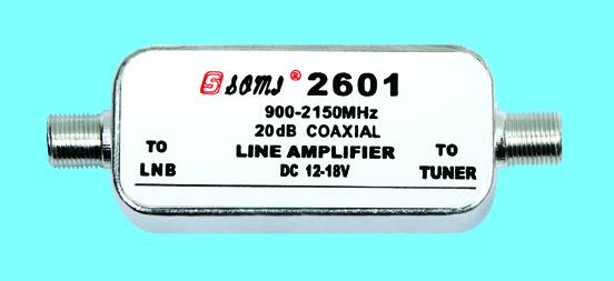
A passive split plus 30 metres of coax can consume 15 to 20 dB, which is more than the receiver's margin on a weak transponder. The 2601 satellite line amplifier covers 900 to 2200 MHz with 18 to 22 dB of gain for exactly this case. It belongs in the IF run, not in the terrestrial path, and it must be powered from a point that does not interrupt the LNB supply.
A specification checklist for satellite distribution
The cheapest way to avoid all of this is to treat the frequency rating as a filter on the quotation, before price is discussed. A splitter that costs less per port but is specified to 1 GHz has not been compared on the same job, and the difference reappears as a service call on the one outlet that feeds a high-band transponder.
Satellite distribution fails in ways that are hard to diagnose after the walls are closed. The checklist below is short enough to apply to every quotation and specific enough to reject a delivery against.
- Splitter rated to at least 2400 MHz with published loss at the top of the band.
- Isolation of 18 dB or better across the full range, not just at 1 GHz.
- DC pass path identified, and matching the LNB powering arrangement.
- Ports terminated where outlets are not yet connected.
- Wall plates specified as diplexed where satellite and terrestrial share a box.
Need this checked against your own signal chain?
Send the number of outlets, the LNB type and the cable lengths, and we will return a satellite IF level budget with the splitter and amplifier models that meet it. Send the details through our inquiry form or reach the team on the contact page.
Request a quotation